EEE3074W:
Embedded Systems
Part B: Experimentation and Modeling

E.B.E.
|
|
EEE3074W:
Embedded Systems
Part B: Experimentation and Modeling
|
E.B.E. |
Scope: This page tells you
about Part B of the EEE3074W project.
This document provides a summary of what is expected for the Project 3 Part B, the design phase. See Figure 1 for UML diagram showing structure the aspects involved in this part of the project.
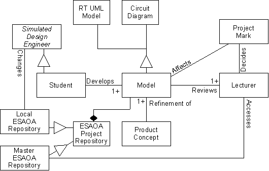
Figure 1: UML diagram of elements for Part B of The Project.
The next milestone involves modeling. The models should focus only on the subsystem to prototype, showing important design decisions and considering its integration / interfacing aspects with the rest of the system.
Each member should be responsible
for two models and they should be initialed by the
author. The group is jointly responsible for use case diagrams
and a circuit diagram, of which a sample can can be submitted
in an entirely rough and ready form. The other diagrams should be
done on computer. You may want to start developing prototype code, and an
initial circuit diagram to help refine the models. Neither the circuit diagram,
not any code will be marked for this milestone; however an initial circuit
diagram needs to be submitted so that I can review it.
Modeling should not be done entirely in
isolation; that is not the idea. The intent is that you should agree
on functionality in the group, perhaps developing rough versions in
the meeting; but the final, more refined version should be drawn up
on computer individually; and will be marked separately from the
group submission. Do not go into excessive depth in the
modeling; time is very limited; you should rather focus on modeling
important aspects of the subsystem, connections to the rest of the
system, especially including refinements for developing the
prototype. Timing and other important QoS requirements should be
indicated in the relevant RT-UML diagrams. Class stereotypes (e.g. Entity,
Control and Boundary) should be indicated.
The following models need to be submitted:
JOINT RESPONSIBILITY
Rough use case diagrams (can be done by hand on paper) – if you have already drawn up rough use case diagrams while developing your concept, you can submit them.
Initial circuit diagram : marked 0 (absent) or 1 (present). Rough version on paper acceptable.
MEMBER 1
Front panel / menu displays (e.g. sample screens, what happens when a button is pressed).
2 sequence diagrams: one showing “sunny day operation”, one an exception.
RECOMMEND CODING: User interface and/or signal processing
MEMBER 2
Class diagram
Interface Control Document (initial version)
RECOMMEND CODING: Comms
MEMBER 3
Statechart
Timing diagram
RECOMMEND CODING: Driver and/or signal processing
In terms of coding, you should consider splitting the work according to:
Driver coding (i.e. talking to a peripheral)
Communications (i.e. implementing a packet protocol, include error detection)
User interface (could simply involve porting your menu application to the CSB337)
Signal processing (sampling and processing of input, generating outputs)
My recommendations as to which member should be responsible for what code modules, are indicated above.
The team leader should a) keep a short log of who was allocated to what model, and b) ensure that each model has been initialed by the author and also indicates the group number.
Use case diagrams should focus on interactions with the subsystem, and of interactions between major components it comprises
The circuit should show how an external peripheral will be connected to the CSB337, indicating ports, pin numbers and component specifications (e.g. resistance values, maximum power ratings, etc)
Class diagram should show major hardware and software components, with suitable associations. You do not need to model down the level of LED1 connecting to GPIO in turn connected to the AIC... etc. You can simply show an LEDDriver driver class contained in the embedded processor.
Statecharts should focus on signal processing (i.e. handling pushbuttons, sensing temperature), and does not need go into detail of handing communications protocols (although it should indicate when communications are handled)
Timing diagram can refine part of the statechart (i.e. show timing between transitions)
Sequence diagram should indicate either the communications or the signal processing aspect; you are not required to do both.
Front panel / menu displays can simply show the menu/ui interaction aspect of a sequence diagram.
Interface control document should be done only for one interface; this could be the communications protocol or the driver used for controlling the external peripheral.
Repository
All teams have a shared repository in the /REPOSITORY/Project1/TEAMn directory, where n is the number of your team. You should keep the MASTER files for your project under the MASTER directory in your repository. Start by putting your initial version of the concept slides in directory MASTER/Concept.
Submissions
Models and circuit diagram can be submitted in separate documents, or in one document. Please ensure the filename contains string TEAMnn where nn is the value 01 to 13 for your team.
If you want to submit multiple documents together using one user (PREFERRED METHOD):
Zip or tar the documents in one zip (or tar.gz) archive file
Name the file TEAMnn.zip (or TEAMnn.tar.gz) where nn is the team number, 01 to 13
In the case of a single document submission (i.e. last minute):
Please ensure the document filename contains TEAMnn
Submit files using the Project3 MODELS task on connect. Only submit one copy of each model.
Navigation: [The Project] [Start] [Prev: Part A] [Next:
Part C]