
YODA Project
Introduction
Teams are planned around being three members. If you need to formulate a team of 2 or 4 then please notify the lecturer (before starting on the project) and an additional element of work (for a team of 4) may need to be added, or a simplification applied (for a team of 2) to make things more fair all round. For teams of three, the workload will be arranged accordingly (together with your 'team manager') so that each student in the class will have a similar workload in terms of time spent on this project.
Choosing a Topic
The procedure for selecting a topic (applicable to registered student taking this course for credit) is to start by looking over the available topics that are offered on this page. If you are inspired to suggest your own idea for a topic, you are most welcome to do so (see Selecting a topic of your own idea below if so). Topic allocation is first come first serve. Take note of the topic number of the project you want to work on. If you don't see any topic that interests you, consider taking a look at the numerical recipes online book or books in the library.
Selecting a Standard Topic
The topic selection process is self administrated. Begin by going to the VULA website for this course, select the Wiki and then select the Yoda Topic groups.
First check to see that no other group has selected the topic your group is planning on. If the topic is already selected, then sorry; please try other option. Alternatively follow the Selecting a topic of your own idea described below (i.e., you could tweak the topic idea to bit a bit different).
If the topic is available then email the lecturer to tell him the topic you have chosen, just a brief email will suffice as in:
Hi, our group (<list student names here>) has chosen topic Pnn (where nn is the number of the project).
This is to record at which time the selection was made in case there are any disagreements between teams as to who was first.
Then, when you have sent the email edit the Wiki and add a new row that will record your and your team members' names and student numbers and indicate the topic title and number in the appropriate columns of the table. Then save the wiki page and now you're done. You are now welcome to proceed with the Blog assignment for the YODA project which records further discussion and initial planning concerning the topic.
Selecting a topic of your own idea
In the case that you want to do your own topic idea, first prepare a short abstract describing the topic. It should follow a structure as given in the topic description on this page. You need 1) a topic title, 2) a textual description of the topic, 3) explanation of inputs and outputs. You can put in figure(s) to help explain the topic, and if you like specific optional additions that might be added if time permits (of course describing the optional additions doesn't mean you will commit to doing them, it is just nice to think about how the topic could be further developed should there be time or interest). It is expected that the project topics can be put in the public domain (if for any reason you disagree with this the please discuss this with the lecture via email or in person to discuss the issue and negotiate a compromise).
Send your abstract to the lecturer for approval and possible modification (i.e., to ensure it has sufficient work at a suitably technical level and won't take too long to complete). Once you have approval you'll be assigned a topic number; then please go ahead and follow the step to record your project team in the Yoda Topic Groups page on the Vula site for this course.
YODA Mini Conference
|
The YODA mini conference is scheduled for the last week of lectures in term 2, which provides an opportunity for each group to present to the other students, and any invited guest, on their YODA project. This is meant as a simulated professional conference where each team will have a short period of time to present their projects - it is required to have slides to present and design details and optional to have a live demo of the prototyped system. The demos should be shown to the lecturer and/or alternate marker (usually after the YODA conference). The conference is scheduled for the afternoon lecture on Tuesday and the double period on Thursday, the timing has to be quite precise. Each student needs to attend at least one other presentation session besides their own so as to provide an audience for another group's presentation. Attendance marks will be allocated, a large part of the project marks is allocated to the YODA presentation. |
 |
YODA Project Topics
- P01: SF - Smoothing Filter
- P02: CAM - Content Addressable Memory
- P03: IF - Interpolation filter
- P04: PRNG - Parallel Random Number Generator
- P05: DM - Delta modulator
- P06: ASG - Arithmetic series generator
- P07: SALG - Selection Address List Generator
- P08: FSG - Function Samples Generator
- P09: BSS - Bit Sequence Sniffer
- P10: BCDC - Binary Coded Decimal Convertor
- P11: NCSM - Nonlinear Check Sum Module
- P12: MD5 - Message Digest version 5
- P13: MMA - Matrix Multiplier Accelerator
- P14: IMA - Image Masking Accelerator
- P15: PSA - Pattern Seek Accelerator
- P16: DE - Data Encryption Accelerator
- P17: VADER - Versatile Accelerated Digital Encryption Recovery
- P18: PADAWAN - Parallel Accelerator for Digitising Audio with Attenuation of Noise
- P19: DDS - Direct Digital Synthesis
P01: SF - Smoothing Filter
Send the src address and len to indicate the starting address of an input sample and its length in words. Also send a dest value to indicate where the smoothed value is to be stored. Toggle the activate bit to perform the smoothing (i.e., could do an average of m elemenents). The SF sets it done bit to true when complete.
Inputs: unsigned src, unsigned len, unsigned dest, bit
activate
Output: bit done
P02: CAM - Content Addressable Memory
Consider a table where each element has the form defined as follows:
struct
TableElement{
unsigned key;
byte record[rsize];
};
The table itself is in the form:
struct TableElement table[nelements];
The CAM accelerator is sent the partial contents of a record and it returns the key, if found. If the contents is not found, the value 0xFFFFFFFF is returned. The user can ask the CAM accelerator to continue searching and find the next occurrence of the given search string.
The rsize member is constant for each element in a table, but multiple tables may exist with different rsize values for each table. The CAM accelerator must be able to store table start index and rsize information so that subsequent uses of the CAM accelerator, when using the same table, does not need to resend the table addressing information.
Inputs: unsigned start, unsigned rsize, unsigned
nelements, bit activate, byte array search string
Output: unsigned key, bit done
P03: IF - Interpolation filter
Tell the IF the start address and len of a src float array to upsample, tell the IF the dst array that is 2x(end-start) elements, tell the IF to start. The IF then adds a value between each sample of src, saving the new sample in array dst (and sets done to true when finished). i.e. the C code would look like this:
int j =
0;
for(i = 0; i < len-1; i++){
dst[j ] = src[j];
dst[j+1] = src[j] + (dst[j+1] - src[j]) / 2.0;
j += 2;
}
As an optional advanced option: make the dst array length Nx(end-start) elements, where N is any positive integer.
Inputs: unsigned start, unsigned dst, unsigned len, bit
start
Outputs: bit done
P04: PRNG - Parallel Random Number Generator
Generate N random numbers in one go. The idea is that the PNRG could write directly to RAM, and a soft processor can access it. Generates numbers in range 0 to 232-1.
Inputs: unsigned seed, unsigned start_address, unsigned
count (i.e., num of random numbers to generate), bit
activate
Output: bit busy
P05: DM - Delta modulator
Send a stream of 8 bytes to the DM device, and it returns 1 byte, where the bits in sequence from lsb to msb represents the delta modulation.
The delta modulator is pretty easy, so you might want to add additional features, for example:
Optional extra feature 1: Make the LEDs on the FPGA board indicate the half wavelength (e.g. for a sinusoidal signal, the delta value is only going to change at the turning points, so counting the number of inputs from one change in delta to the next, and showing that number of the LEDs, will give a approximation for the wavelength).
Optional extra feature 2: Add flow control. Assume that the DM might take a long time to complete. So, in this case, the processor needs to wait for the DM to be ready for input, then send the input, waits for the result, and then goes back to waiting for the DM to be ready for more input. You could add pushbutton control to either clock the DM or to control how fast it is clocked. The combination of Extra feature 1 and 2 will make it easier for humans to see the LEDs display wave length information.
Inputs: byte byteIn, bit clock
Output: modOut
P06: ASG - Arithmetic series generator
This accelerator generates the series:
a(n) = a1 + (n-1)d
The inputs saddr indicates the starting address in memory where the generated sequence is to be stored. A activate input bit will be needed to tell the ASG to start processing; the ASG will return done when complete.
Inputs: float a1, float d, unsigned n, unsigned saddr,
bit activate
Outputs: done
P07: SALG - Selection Address List Generator
The SALG is sent the starting address of a table in memory. The table has n elements. Each element of the table is in the form TableElement shown below. The SALG is sent a second address, called inds, which it will use to store the addresses (i.e., the starting address of the relevant record field) that matches the selection criteria (which is hardcoded).
struct
TableElement{
unsigned key;
byte record[rsize];
};
TableElement table[n];
Example implementation of SALGA function that returns the address of all records that have odd numbered keys:
void
SALGA(TableElement* table, unsigned* inds, unsigned n){
unsigned n_inds = 0;
for(int i = 0; i < n; i++){
if(table[n]->key & 1)
inds[n_inds++] =
&table[n]->record[0];
}
inds[n_inds] = 0; // set last one to null to
indicate end of list
}
As is the case with the other accelerators, an activate input and done output would be needed.
Inputs: unsigned table, unsigned n, unsigned inds, bit
activate
Outputs: bit done
P08: FSG - Function Samples Generator
The FSG is used to generate a sequence of samples from a hard-coded function. The FSG is given two float inputs,xstart and xend, which indicates the range for the x values that you want to samples for the function, as well as an unsigned nsamp input indicating the number of samples you want to obtain. A fourth parameter, p indicates the memory address to write the sampled values to.
The FSG implements a FPGA equivelent of the following C code. Note that the function fn would be hard-coded, it's just easier to show a function there to help the explanation in C.
void
FSG(float xstart, float xend, unsigned nsamp, float* p){
unsigned i;
done = 0; // clear the done signal
for(i = 0; i < nsamp; i++){
p[i] = fn(xstart + i*(xend-xstart) /
nsamp);
}
done = 1; // raise the done signal to indicate
to the
//
softprocessor that the operation is finished
}
float fn(float x){
// This example just returns a polynomial
return 5*x*x + 3*x;
}
Inputs: float xstart, float xend, unsigned nsamp, float*
p, bit activate
Outputs: bit done
P09: BSS - Bit Sequence Sniffer
The Bit Sequence Sniffer (BSS) device is connected onto a series binary data transmission line, for example a RS232 data line or (with an appropriate differential signal demodulator unit) onto data lines of a USB connector. A "sniffer" device has many real-world applications, and these type of things exist in reality.
"Data sniffers" can generally be divided into a variety of types, such as: transmission line sniffers, debug sniffers, security sniffers, self-diagnostic sniffer module. Transmission line sniffers are perhaps the most general case; these could for example simply record data that is sent along data lines - these would generally be used for reputable purposes such as monitoring utilisation levels of connections. Debug sniffers could for instance be JTAG-like devices that could be used to gain useful debugging data, for example checking that the bits sent from an ADC to the CPU are all successfully obtained by the CPU. Security sniffers have many applications, for example to detect threats to a network (e.g., a computer jamming the network with junk messages, or probing attacks from an unrecognised IP or stack overflow attacks).
Basic sniffers are not particularly complex pieces of equipment, but they generally need to operate at high speed in order to capture the bits of data. For this project, the objective is to develop a RS232 transmission line sniffer that will be able to connect to either the RX or TX line and be able to capture bytes of data sent. To simplify things, the protocol can be assumed to be something easy like one start bit, 8 data bits, 1 parity and 1 stop bit (i.e., 11 bits per 8 bytes of data sent). Added to this should be detecting a particular sequence, say a series of bytes such as {0xA0, 0xB5, 0xFF}; and if such a sequence is detected, then a LED flashes. If time permits, a more sophisticated version could be constructed that detects a start sequence (e.g., 0xA0} and then captures the next 10 bytes and sends them out the USB / debug channel to be displayed on the attached PC.
A small breadboard circuit will likely be needed in order to adjust voltage levels for the sniffer if one of the PIO pin on the FPGA is going to be used to sense the input.
Notes on inputs and outputs:
| SniffIn | this would be the input bit connected to one of the RS232 RT/TX data lines. |
| Seqdetect | output bit (to turn on LED also) to record that a preprogrammed sequence was detected. |
| DataOut | ability to dump a suspect sequence to a connected PC for recording (i.e., for if the last part of the description above is implemented). |
P10: BCDC - Binary Coded Decimal Convertor
The BCDC converts a binary integer of arbitrary length to a sequence of binary coded decimal digits. Inputs to the device are a starting address, input src, and len indicating the number of bytes to convert. A third input dst indicates the address where the converted values are stored. As with the other proposed projects, when the active input changes from low to high, the BCDC starts, and then raises the done output to indicate completion.
Notes on inputs and outputs:
Assume the input integer 2 882 400 018 (0xABCDEF12 hex). This input is 4 bytes long and the output is 10 nibbles (5 bytes): array bcd = {0010, 1000, 1000, 0010, 0100, 0000, 0000, 0000, 0001, 1000} // note each element is in base 2
It is your choice to use either little endian or big endian representation.
P11: NCSM - Nonlinear Check Sum Module
Most checksums are simple, just summing each input value, call it x(n) that comes in; so the function would read something like y = Sum x(n) for n = 1..n.
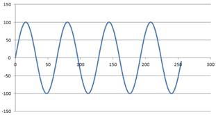
This project aims to experiment with nonlinear checksums functions as a means to create a check value that is perhaps more robust but also more platform specific. The NCSM project probably sounds quite simple, and for the most part is. It implements 32-bit fixed point calculations of the input steam of bytes sent to the NCSM module. If you'd prefer a more intense challenge (that would also improve performance and look more impressive), then attempt to do the checksum on a block of RAM memory. The nonlinear function, called funct below must be implemented to account for wrapping and suitable use of mapping a 8-bit input to the 32-bit output range.
The implementation in C-style pseudocode is as follows:
unsigned
funct(input byte x, output unsigned y){
y = 100*sin((x-128)*M_PI/32);
}
void checksum(
input byte x,
input bit reset,
input bit clk,
output unsigned result
){
static unsigned sum = 0;
if(reset clocked){
sum = 0;
return;
}
if(clk clocked){
sum += funct(input, n);
result = sum;
}
}
A graph of the suggested funct is provided below:
Inputs: unsigned x, bit reset, bit clk
Outputs: unsigned result
P12: MD5 - Message Digest version 5
MD5 is a standard hashing algorithm most frequently used to verify the contents of large files. More information can be found on Wikipedia
Inputs: stream of data to be verified
Outputs: unsigned MD5 sum
P13: MMA - Matrix Multiplier Accelerator
The MMA works on square matrices (if you feel inspited, you can revise it to work on appropriately sized rectangular matrices). Two memory addresses are passed to MMA, namely A and B, in indicate the starting addresses of the matrices to be multiplied. A third memory address, C indicates the address to save the resultant matrix. Input n indicates the size of the matrices. Assume the matrices contain floats. Assume that the matrix elements are indexed in the standard way, i.e.:
index of A(i, j) = j*n + i (where i and j are in the range 0 to n-1)
The activate bit input will be clocked to tell the MMA to start multiplying. The MMA will raise the done output high when it is complete.
P14: IMA - Image Masking Accelerator
The IMA overlays an image mask on a larger image by using the XOR operation. Assume both the mask and the larger image are in RGB 12-bit color (4-bit per component) uncompressed format, at a resolution of 320 x 240. The result is displayed on a VGA screen.
Inputs:
| mask | address of the image mask in memory |
| mw, mh | width and height in pixels of the mask |
| mx, my | (x, y) offset from top left of image that the mask is to be applied |
| img | the image that the mask is to be overlaid |
| iw, ih | the width and height in pixels of the image |
| activate | bit input to be clocked to activate the IMA |
Outputs:
| done | set high once the mask has been overlaid |
Note: This project is designed with a Nexys 4 in mind, which has 4 860 kbit on-chip memory. For optimal RAM usage, the RAM blocks can be configured to have a word width of 36-bit.
P15: PSA - Pattern Seek Accelerator
The PSA searches for a particular sequence of bytes in a block of memory.
Inputs:
| unsigned p | the pattern to be searched for |
| unsigned pl | length of the pattern in bytes |
| unsigned b | address of the block of memory to searh |
| unsigned bl | number of bytes in b |
| it activate | clock to activate the PSA and tell it to continue searching from last address |
| bit reset | set b and clock reset to tell the PSA to start searching from address b |
Outputs:
| bit done | the PSA sets this to high when it is complete |
| unsigned found | that the pattern started at (note that you might find it easier to set found to pl + the start of the pattern that was found. found could be set to 0xFFFFFFFF if nothing was found, otherwise you could add a success bit to indicate if the pattern was found. |
Simplification: if you want, you can simplify the topic. For example, the PSA could just respond with a found set to 1 or 0 depending whether the pattern was found. Further simplifications could be to look for a single byte in a block of memory (i.e., only using one address input, namely b).
Example operation
Assume:
- p = 0xFF00, pl = 2
- b = 0xFF10, bl = 8
- memory location 0xFF00 = {101, 102}
- memory location 0xFF10 = {99, 100, 101, 102, 103, 101, 102, 100}
Steps:
- First p will be reset
PSA.b = 0xFF10; PSA.reset = 0; PSA.reset = 1; PSA.reset = 0; - Next the inputs are specified
PSA.p = 0xFF00; PSA.pl = 2;
PSA.b = 0xFF10; PSA.bl = 8; - The activate is clocked
PSA.activate = 0; PSA.activate = 1; PSA.activate = 0; - The PSA now proceeds to do the first search
PSA.done = 1; PSA.found = 0xFF12; - The PSA is clocked again to continue the search
PSA.activate = 0; PSA.activate = 1; PSA.activate = 0; - Another match was found
PSA.done = 1; PSA.found = 0xFF15; - The PSA is clocked again to continue the search
PSA.activate = 0; PSA.activate = 1; PSA.activate = 0; - No more matches
PSA.done = 1; PSA.found = 0xFFFFFFFF;
P16: DE - Data Encryption Accelerator
The objective the Data Encryption Accelerator (DEA) is to accelerate the process of encrypting a data stream. First the (reset) control line is clocked, this causes the DEA to reset any internal buffers and storage. Next, an encryption key is set by writing the (a single byte value) of the key to the din (data input) 8-bit data input bus, and then sending a positive edge to the kset (key set) control line. The dclk (data clock) is kept low. After this, the actual encryption starts, which involves iterating through all the data, one byte at a time, by writing a byte of data to the din input lines, then clock dclk clock line. The encrypted data is (pretty much) immediately available on the DEA's dout 8-bit output lines. The latter process is repeated for each item of data.
To start with, you could use simple XOR encryption. If time permits, you could then take it further using some sort of repeating pattern based on the key input.
P17: VADER - Versatile Accelerated Digital Encryption Recovery
The VADER system is a digitally accelerated add-on hardware device designed to recover passwords using an acquired hashed password and hashing function. Uses of such a device could be to speed up computationally expensive recovery of passwords for forensic purposes such as instances where a victim or suspects password protected information could assist in an investigation. In order for the system to begin the specific hashing function used to create the password hashes would need to be acquired; it is assumed that this is available and many commonly used hashing functions are indeed widely available. The hashed version of the password itself would also need to be acquired. The system will run parallelised functions on an FPGA to accelerate the recovery of the password. The system will first run a dictionary type cracking attempt and following this if it is unsuccessful a brute force algorithm will be applied. A schematic flow diagram of how the system operates is shown below.
P18: PADAWAN - Parallel Accelerator for Digitising Audio with Attenuation of Noise
The problem to be solved is performing filtering and processing on audio in near real-time using an FPGA
Real-time filtering can be achieved in software, however when many filters are cascaded one after the other (or in parallel in the case of an equaliser) there will be a delay between audio input and output. For many applications this is an undesirable side-effect, preventing the system from being considered real-time.
Some types of filters that can be implemented are: low-pass, high-pass, band-pass and band-stop. Some effects that can be implemented are: echo, flange, chorus, reverberation, vibrato, phaser, delay and distortion. The user should be able to change the filter and effect parameters (in real-time) and hear the effect on the audio output.
The PADAWAN system is provided with a digital audio stream and output is converted to analogue by means of pulse width modulation (PWM). If time permits, the output must also pass through a noise shaper in order to increase the apparent output resolution.
Note: This project is intended for Nexys 4, which has an on-chip ADC and on-board PWM filter.
Inputs: Audio stream, filter and effect parameters
Output: PWM audio
P19: DDS - Direct Digital Synthesis
Direct digital synthesis is a digital signal processing technique by which arbitrary waveforms can be generated. The DDS module is given a waveform definition (in the form if a look-up table), a frequency word and an amplitude word.
For the purposes of this project, the output is in the audio frequency band and converted to analogue by means of pulse width modulation (PWM). If time permits, the output must also pass through a noise shaper in order to increase the apparent output resolution.
Implementation of this project will start with the generation of a variable-frequency saw-tooth signal, which will eventually become the input of the look-up table.
Inputs: waveform definition, unsigned frequency, unsigned
amplitude
Output: PWM audio
